
|
| Place of Origin | CHINA |
| Brand Name | BEITE |
| Certification | CE ISO |
| Model Number | BT590178 |
Description
I. Overview
TFS-800 flow switch is a measuring instrument that can monitor the liquid flow in the pipeline in real time and provide signal output. This product adopts a full metal shell with no moving parts. The switching value can be continuously adjusted on site, with small pressure loss and compact structure. Multiple LEDs can display the flow status and switching status in real time. Easy to install, the product is suitable for a variety of pipe diameter requirements and can be used to monitor the flow rate of fluids in pipelines, monitor flow interruptions, or protect pumps from idling. It is widely used in hydropower industry, industrial hydraulic industry and other places where pipeline fluid flow rate monitoring is required.
2. Performance parameters
Measuring range: 1~150cm/s (water), 3cm/s~300cm/s (oil)
200~3000cm/s (gas)
u Working voltage: 24±20%VDC;
u Current consumption: <90mA;
u Signal output: relay (SPDT), PNP transistor;
Transistor Characteristics:
u Switching voltage: 24±20%VDC;
u Switching current: ≤1.2A;
Relay characteristics:
u Switching voltage: ≤250VAC/30VDC;
u Switching current: ≤3A;
u Initialization time: typical value 8s (2~15s);
u Response time: typical value 2s (1~15s);
u Temperature gradient: upper limit 250℃/min;
u Protection level: IP67
u Medium temperature: -20~80℃;
u Ambient temperature: -10~70℃;
u Storage temperature: -20~85℃;
u Pressure resistance level: 10MPa;
u Probe material: 304 stainless steel
u Shell material: 304 stainless steel
3. Product application
The sensing component and signal processing unit of this product are integrated structures, and the flow rate monitoring settings are continuously adjusted. The monitoring range is related to the flow rate, and has nothing to do with the flow rate or the overall flow rate. This product is used for monitoring functions in the following aspects: (1) Medium flow/lower flow rate;
(2) The presence/absence of the medium; (3) The flow/stationarity of the medium.
This product uses 6 indicator lights of different colors arranged in a row on the panel to display the alarm status and flow rate trend, and outputs switching signals through a single relay. The meanings of the 6 indicator lights are as follows:
1 red indicator light: when lit, the set flow rate has not been reached;
![]()
1 yellow indicator light: when lit, the set flow rate is reached/exceeds the set flow rate, and the relay starts to act;
![]()
4 green indicator lights: When the set flow rate is exceeded, they light up in sequence. The more lights on, the greater the flow rate. When the flow rate decreases, they go out in reverse order.
![]()
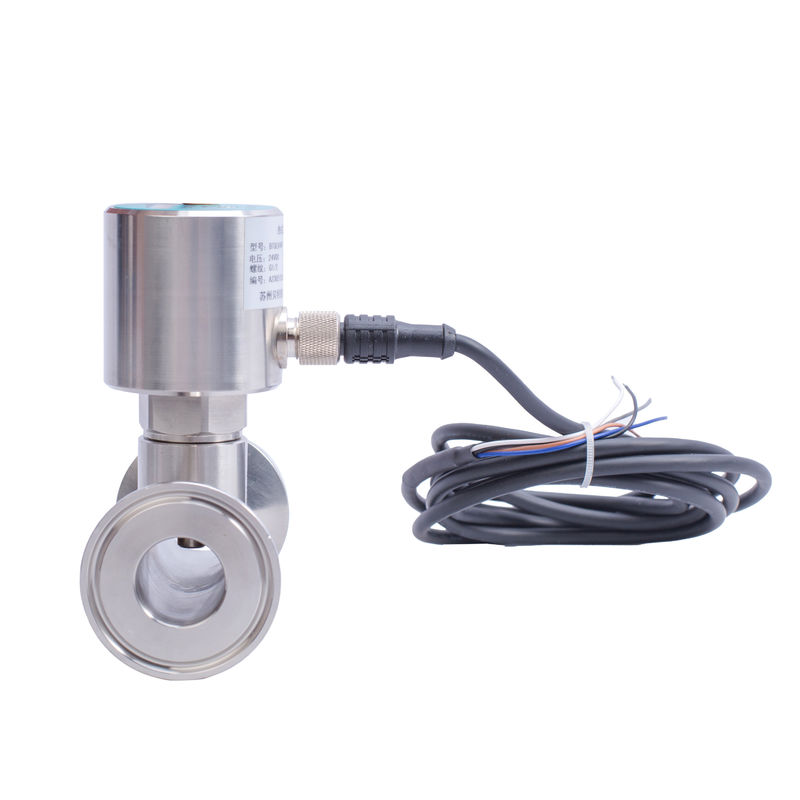
4. Appearance structure and electrical definition
The flow switch adopts cable or connector connection method. Its appearance is shown in Figure 1.
Structural dimension drawing:
![]()
Electrical definition: M12*1 aviation plug
![]()
Table 1 Electrical Definition
Wiring diagram
![]()
![]()
5. Product installation
1. When installing the product, the probe needs to be completely immersed in the fluid. If installed on a small pipe diameter, be careful to use appropriate methods to avoid pushing the probe against the pipe wall below.
2. When the fluid cannot completely fill the pipe, the product needs to be installed at the bottom of the pipe (Figure 3)
![]()
3. If there may be sediment in the pipe, please install the product on the side wall of the pipe, install it horizontally (Figure 4), and avoid air and sediment.
![]()
4. When installing the product on a straight pipe away from a bend or intersection, the length of the straight pipe should not be less than 4 times the pipe diameter.
6. Product adjustment
After the product is installed on the pipe, please connect the wires according to the electrical connection. Turn on the power and wait for the product to work stably for 2 minutes before starting to adjust.
![]()
As shown in Figure 5, unscrew the dust-proof screw on the upper end of the product and you can see the adjustment end of the potentiometer. Stand at the outlet end of the product and use a flat-head screwdriver to rotate the adjustment end of the potentiometer clockwise. The indicator light will go from left to right. Lights up in sequence, and goes out in turn. For different applications, follow the steps below to adjust. If the adjustment effect is not satisfactory at one time, you can repeat the adjustment multiple times. Note that when adjusting the setting, wait for the fluid to flow stably for 15 to 30 seconds before adjusting the potentiometer every time the flow rate changes.
●Media flow/reduce flow rate
1. Establish a lower limit flow rate or a standard flow rate lower than the set monitoring flow rate;
2. Adjust the potentiometer to make the red LED light on;
3. Restore the flow rate to be controlled, make the medium flow at the flow rate that needs to be monitored, and adjust the potentiometer so that the yellow indicator light and at least one green indicator light are on.
●Media is still/flowing
Adjust the potentiometer so that when the pipeline medium does not flow, the red indicator light will light up. When the medium reaches a certain flow rate, the yellow and at least one green indicator light will light up.
●Media exists/does not exist
Adjust the potentiometer so that when there is no medium in the pipeline, the red indicator light will be on. When there is medium in the pipeline or a certain flow rate is reached, the yellow and at least one green indicator light will be on.
7. Precautions
Please read this manual carefully before use and make correct wiring according to the electrical connection of the product.
Before connecting the power supply, make sure that the power supply voltage is within the power supply range of the product. High voltage may damage the product;
Pay attention to the direction and method of installing the product.
8. Responsibility
Within one year from the date of shipment, our company will replace or repair products with quality defects caused by material and workmanship problems free of charge; for product failures caused by non-quality reasons during use, our company will be responsible for repairs and only charge the material cost. fee.
Packing & Delivery
![]()
FAQ
1. Q: What information need to be provided to choose the suitable model?
A: Application field, Nominal pressure ,Medium & medium temperture , Power supply , Output,
Flow range, Accuracy, Connection and other parameters.
2. Q: Are you a trade company or a manufacturer?
A: We are an ISO approved manufacturer specialized in level and flow measuring instruments.
OEM & ODM service are available. Welcome to visit us in China.
3. Q: What is your MOQ?
A: To start our cooperation, sample order is acceptable.
4. Q: What is your delivery date for the Intelligent Mini Micro Turbine Fuel Oil Diesel Flow Meter?
A: The delivery date is about 3-15 working days after receipt of payment.
5. Q: What is your payment terms?
A: We support T/T, PayPal ,Western Union.
For mass production order, it is 30% deposit in advance and 70% balance before shipment.
6. Q: Do you have a warranty for the Flow Meter?
A: Yes, we have the warranty of 12 months.
Contact Us at Any Time


