
 Home
>
products
>
Pressure Instrument
>
Home
>
products
>
Pressure Instrument
>
|
| Place of Origin | CHINA |
| Brand Name | BEITE |
| Certification | CE ISO |
| Model Number | RP62 Series |
Description
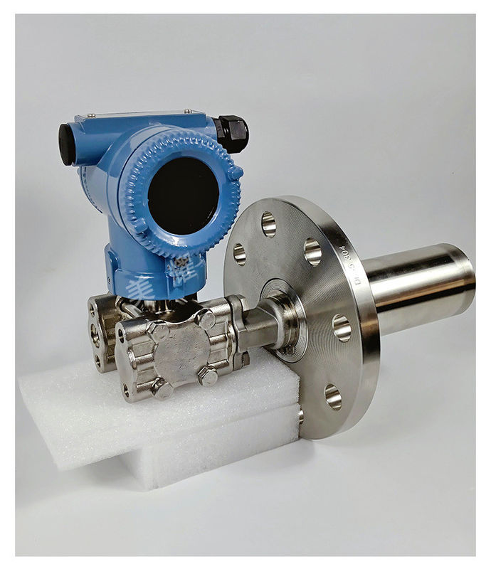
For pressure/differential pressure transmitters, there are two mounting brackets available, and the installation method is the typical installation method. Secure the pressure transmitter to the mounting bracket with the 4 bolts provided. Then fix the pipe-mounted bracket (B1) and the transmitter on a horizontal or vertical pipe of about φ50mm through U-shaped bolts or fix the panel-mounted bracket (B2) on the instrument panel with M10 bolts (prepared by the user). To facilitate the connection of the flange or transition joint with the pressure piping, the direction of the transmitter can be rotated. If the flange remains vertical after rotation, there will be no change in the zero point. If the flange is turned to a horizontal position, the resulting change in zero point is equal to the liquid level difference caused by the change in position.
Check whether the power supply of the differential pressure transmitter is connected reversely and whether the positive and negative poles of the power supply are connected correctly. Measure the power supply of the transmitter to see if there is 24V DC voltage; it must be ensured that the power supply voltage supplied to the transmitter is ≥12V (that is, the voltage at the input terminal of the transmitter power supply is ≥12V). If there is no power supply, check whether the circuit is disconnected, whether the detection instrument is selected incorrectly (input impedance should be ≤250Ω), etc. If the pressure transmitter is equipped with a meter head, you need to check whether the meter head is damaged (you can short-circuit the two wires of the meter head first. If the short circuit is normal, it means the meter head is damaged). If the meter head is damaged, you need to Replace the header. If there is a problem with the differential pressure transmitter, you can connect an ammeter in series to the 24V power supply circuit to check whether the current is normal. If it is normal, it means the transmitter is normal. At this time, you should check whether other instruments in the loop are normal. Check whether the power supply is connected to the power input end of the transmitter, and connect the power cord to the power connection port.
Specification
● Wide measuring range: 0-0.2kpa~41.37Mpa;
● The accuracy is better than 0.075 level, and the range ratio is better than 100:1;
● It truly realizes electrical isolation, reduces the impact of grounding, and improves anti-interference performance.
● Enhanced anti-interference design, strong on-site anti-interference ability.
● The core circuit of the smart transmitter is all built-in sensors and encapsulated as a whole, making the transmitter highly reliable.
● Minimal temperature drift: When performing temperature compensation on the transmitter, the circuit board and sensor perform unified temperature compensation in the same temperature field, so the compensation effect is better and the temperature drift is further reduced;
● Zero point and span adjustment do not affect each other;
● Powerful on-site configuration functions: zero point, full scale, display, unit, upper and lower range limits, damping, etc. are adjustable.
● High-brightness backlit LCD display for easy reading in dark environments. The display head can be rotated 360° to facilitate on-site observation;
● The sensor has non-volatile memory;
● Good stability, high precision, adjustable damping, and strong one-way overload resistance;
● Two-wire system, compliant with HART® protocol.
● No mechanical transmission parts, less maintenance work, strong and vibration-resistant;
● The diaphragm material contacting the medium is optional, and the explosion-proof shell is optional;
|
Pressure Range
|
|
|
Nominal Range
|
-100kPa, 35kPa, 70kPa, 100kPa, 160kPa, 250kPa, 400kPa, 600kPa, 1MPa, 1.6MPa, 2.5MPa, 4MPa, 6MPa, 10MPa, 16MPa, 25MPa, 40MPa,
60MPa, 100MPa |
|
Pressure Reference
|
Gauge pressure | Absolute pressure | Sealed gauge pressure
|
|
Overpressure
|
300%F.S.(≤70kPa) | 200%F.S.(<25MPa) | 150%F.S(≥25MPa)
|
|
Output Signal
|
|
|
Output
|
4 to 20mA + Hart protocol | 4 to 20mA + RS485-MODBUS
|
|
Specification
|
|
|
Accuracy (linearity, hysteresis and repeatability)
|
±0.5%F.S.(typical)
|
|
Supply
|
24VDC(typical)
|
|
Compensated Temp.
|
-10ºC - 70ºC(typical)
|
|
Medium Temp.
|
-30ºC - 100ºC
|
|
Ambient Temp.
|
-40ºC - 85ºC
|
|
Storage Temp.
|
-40ºC - 125ºC
|
|
Zero Temp. Coefficient
|
±1.5%F.S.max.(@-20ºC - 85ºC)
|
|
Sensitivity Temp. Coefficient
|
±1.5%F.S.max.(@-20ºC - 85ºC)
|
|
Housing material
|
Copper aluminum alloy
|
|
Sensor material
|
Stainless steel 316L
|
|
Protection
|
IP65
|
|
Weight
|
Approx.(1500g)
|
Packing & Delivery
![]()
FAQ
1. Q: What information need to be provided to choose the suitable model?
A: Application field, Nominal pressure ,Medium & medium temperture , Power supply , Output,
Flow range, Accuracy, Connection and other parameters.
2. Q: Are you a trade company or a manufacturer?
A: We are an ISO approved manufacturer specialized in level and flow measuring instruments.
OEM & ODM service are available. Welcome to visit us in China.
3. Q: What is your MOQ?
A: To start our cooperation, sample order is acceptable.
4. Q: What is your delivery date for the Intelligent Mini Micro Turbine Fuel Oil Diesel Flow Meter?
A: The delivery date is about 3-15 working days after receipt of payment.
5. Q: What is your payment terms?
A: We support T/T, PayPal ,Western Union.
For mass production order, it is 30% deposit in advance and 70% balance before shipment.
6. Q: Do you have a warranty for the Flow Meter?
A: Yes, we have the warranty of 12 months.
Contact Us at Any Time

